
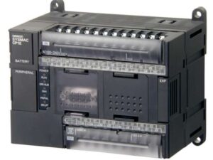
CJ2M-MD211
Mô đun xung CJ2 Omron
Pulse I/O Functions
The following functions of CJ2M can be used by installing one or two Pulse I/O Modules. Each module has 10 high-speed inputs and 6 high-speed outputs. Pulse I/O Modules can be installed on CJ2M CPU Units with Unit Version 2.0 or Later.
- The inputs can be used as general-purpose inputs, interrupt inputs, quick-response inputs, high-speed counters, or origin search inputs.
- The outputs can be used as general-purpose outputs, pulse outputs, origin search outputs, or PWM outputs.
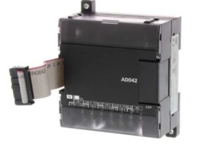
One Pulse I/O Module can be mounted
![CJ2M-CPU3[] / CPU1[] / MD21[] Specifications 8](http://www.ia.omron.com/Images/2712_sp_413-110168.gif "CJ2M-MD211 Mô đun xung CJ2 Omron 3")
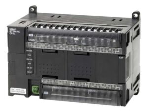
Two Pulse I/O Modules can be mounted
![CJ2M-CPU3[] / CPU1[] / MD21[] Specifications 9](http://www.ia.omron.com/Images/2712_sp_513-110170.gif "CJ2M-MD211 Mô đun xung CJ2 Omron 4")
Note: The Pulse I/O Module closest to the CPU Unit is Pulse I/O Module 0 and the other one is Pulse I/O Module 1.
Performance Specifications
| Item | Description | ||
|---|---|---|---|
| Pulse I/O | Model of Pulse I/O Modules | CJ2M-MD211 (Sinking-type) CJ2M-MD212 (Sourcing-type ) | |
| External Interface | 40-pin MIL connector | ||
| Pulse Inputs | Can be used as normal inputs, interrupt inputs, quick-response inputs, or high-speed counter inputs. (Function of each input must be selected in the PLC Setup.) Input method: Line-driver input or 24-VDC input (selected by wiring) | ||
| Normal Inputs | 20 max. (10 per Pulse I/O Module) Input constants: Set in the PLC Setup (0, 0.5, 1, 2, 4, 8, 16, or 32 ms). Default: 8 ms | ||
| Interrupt Inputs and Quick-response Inputs | 8 max. (4 per Pulse I/O Module) Input signal minimum ON pulse width: 30 μs | ||
| High-speed Counter Inputs | 4 max. (2 per Pulse I/O Module) Input method: Differential-phase (×4) pulses, pulse + direction, up/down pulses, or increment pulse Maximum response frequency: 50 kHz for differential phases or 100 kHz for single phase Counting mode: Linear mode or circular (ring) mode Count value: 32 bits Counter reset: Phase Z + software reset or software reset Control method: Target-value comparison or range comparison Gate function: Supported | ||
| Pulse Outputs | Can be used as normal outputs, pulse outputs, or PWM outputs. (Function of each output must be selected in the PLC Setup.) Output method: Sinking or sourcing transistor outputs (The method is determined by Pulse I/O Module model.) | ||
| Normal Outputs | 12 max. (6 per Pulse I/O Module) | ||
| Pulse Outputs | 4 max. (2 per Pulse I/O Module) Output method: CW/CCW or pulse + direction (The method is determined by the I/O wiring and the instructions used in the ladder program.) Output frequency: 1 pps to 100 kpps (in increments of 1 pps) Output Mode: Continuous mode (for speed control) or independent mode (for position control) Output pulses: Relative coordinates: 0000 0000 to 7FFF FFFF hex (0 to 2,147,483,647 pulses) Absolute coordinates: 8000 0000 to 7FFF FFFF hex (-2,147,483,648 to 2,147,483,647) Acceleration/deceleration curves: Linear or S-curve Origin search function: Supported | ||
| PWM Outputs | 4 max. (2 per Pulse I/O Module) Output frequency: 0.1 to 6,553.5 Hz (in 0.1-Hz increments) or 1 to 32,800 Hz (in 1-Hz increments) Duty ratio: 0.0% to 100.0% (in 0.1% increments) | ||
Function Specifications
| Functions | Description | |||
|---|---|---|---|---|
| Pulse I/O Functions | Pulse Input Func- tions | Normal Inputs | Input signals are read during I/O refreshing and stored in I/O memory. | |
| Interrupt Inputs | An interrupt task can be started when an input signal turns ON or turns OFF. | |||
| Quick-response Inputs | Input signals that are shorter than the cycle time are read and stored in I/O memory. | |||
| High-speed Counter Inputs | High-speed pulse signals are counted. Interrupt tasks can also be started. | |||
| Pulse Output Func- tions | Normal Outputs | The status of I/O memory is output during I/O refreshing. | ||
| Pulse Outputs | A pulse signal is output with the specified frequency and number of pulses at a fixed duty ratio (50%). | |||
| PWM Outputs | A pulse signal is output at the specified duty ratio. | |||
| Origin Searches | The origin point of the machine is determined according to the specified origin search parameters while actually outputting pulses and using the origin and origin proximity input signals as conditions. (Pulse inputs and outputs are also used for this function.) | |||
| Interrupt | Input Interrupt Function | A task is started for an interrupt input from a Pulse I/O Module or for a high- speed counter input. | ||
| Input Interrupts | Interrupt tasks are executed when the interrupt input turns ON or turns OFF. Direct Mode: An interrupt task is executed each time an input signal changes. Counter Mode: Changes in the input signal are counted up or down and the interrupt task is executed when the counter counts out. (The maximum response frequency is 3 kHz.) | |||
| High-speed Counter Interrupts | An interrupt task is executed when preset comparison conditions for a high- speed counter are met. Target-value comparison: The interrupt task is executed when the count matches a specified value. Range comparison: The interrupt task is executed when the count enters or leaves a specified range of values. | |||
Pulse Input Functions
Interrupt Inputs
| Item | Direct Mode | Counter Mode |
| Number of interrupt inputs | Max. | |
| Allocated bit | CIO 2960 and CIO 2962, | |
| Interrupt detection method | ON- | |
| Interrupt task numbers | 140 to 147 ( | |
| Counting method | – | Incrimenting or decrementing ( |
| Counting range | – | 0001 to FFFF hex ( ( |
| Response frequency | – | Single- |
| Storage locations for PVs for interrupt inputs in Counter Mode | – | A536 to A539 and A548 to A551 |
Quick-response inputs
| Item | Specifications |
|---|---|
| Number of Quick-response inputs | Max. 8 inputs |
| Quick-response inputs | Signals that are shorter than the cycle time are latched for one PLC cycle, so they can be detected in the PLC program. Minimum detectable pulse width is 30 μs. |
High-speed Counter Inputs
| Item | Description | ||||
|---|---|---|---|---|---|
| Number of High-speed Counter Inputs | Max. 4 inputs | ||||
| Pulse input method (counting mode) | Incremental pulse inputs | Differential phase input (4×) | Up/down inputs | Pulse + direction inputs | |
| Input signals | Increment pulse | Phase A | Up pulse | Pulse | |
| — | Phase B | Down pulse | Direction | ||
| — | Phase Z | Reset | Reset | ||
| Frequency and number of high-speed counters | 100 kHz, 2 inputs × 2 I/O Modules | 50 kHz, 2 inputs × 2 I/O Modules | 100 kHz, 2 inputs × 2 I/O Modules | 100 kHz, 2 inputs × 2 I/O Modules | |
| Counting mode | Linear mode or ring mode | ||||
| Count value | Linear mode: 8000 0000 to 7FFF FFFF hex 0000 0000 to FFFF FFFF hex (for increment pulse) Ring mode: 0000 0000 to Max. ring value | ||||
| High-speed counter PV storage locations | High-speed counter 0: A271 (upper 4 digits) and A270 (lower 4 digits) High-speed counter 1: A273 (upper 4 digits) and A272 (lower 4 digits) High-speed counter 2: A317 (upper 4 digits) and A316 (lower 4 digits) High-speed counter 3: A319 (upper 4 digits) and A318 (lower 4 digits) Refreshed during overseeing processing. Use PRV(881) to read the most recent PVs. | ||||
| Data format: 8 digit hexadecimal Linear mode: 8000 0000 to 7FFF FFFF hex 0000 0000 to FFFF FFFF hex (for increment pulse) Ring mode: 0000 0000 to Max. ring value | |||||
| Control method | Target value comparison | Up to 48 target values and corresponding interrupt task numbers can be registered. | |||
| Range Comparison | Up to 8 or up to 32 ranges can be registered, with a separate upper limit, lower limit, and interrupt task number for each range. | ||||
| Counter reset method | Phase-Z + Software reset The counter is reset when the phase-Z input goes ON while the Reset Bit (A531.00 to A531.03) is ON. Software reset The counter is reset when the Reset Bit (A531.00 to A531.03) is turned ON. Operation can be set to stop or continue the comparison operation when the high-speed counter is reset. | ||||
Pulse Output Functions
Position Control and Speed Control
| Item | Specifications |
|---|---|
| Number of Pulse Outputs | Max. 4 outputs (Pulse Output 00 to 03) |
| Output mode | Continuous mode (for speed control) or independent mode (for position control) |
| Positioning (independent mode) instructions | PULS (886) and SPED (885), PULS (886) and ACC (888), or PULS2 (887) instruction |
| Speed control (continuous mode) instructions | SPED (885) and ACC (888) instructions |
| Origin (origin search and origin return) instructions | ORG (889) instruction |
| Interrupt feeding instruction | IFEED (892) instruction |
| Output frequency | 1 pps to 100 kpps (1 pps units), two pulse outputs × 2 Pulse I/O Modules |
| Frequency acceleration and eceleration rates | Set in increments of 1 pps for acceleration/deceleration rates from 1 to 65,535 pps (every 4 ms). The acceleration and deceleration rates can be set independently only with the PLS2 (887) instruction. |
| Changing SVs during instruction execution | The target frequency, acceleration/deceleration rate, and target position can be changed. |
| Pulse output method | CW/CCW or pulse + direction |
| Number of output pulses | Relative coordinates: 0000 0000 to 7FFF FFFF hex (Accelerating or decelerating in either direction: 2,147,483,647) Absolute coordinates: 8000 0000 to 7FFF FFFF hex (-2,147,483,648 to 2,147,483,647) |
| Relative/absolute coordinate specifications for pulse output PVs | Absolute coordinates are specified automatically when the origin location has been defined by changing the pulse output PV with the INI (880) instruction or performing an origin search with the ORG(889) instruction. Relative coordinates must be used when the origin is undefined. |
| Relative pulse/absolute pulse specifications | The pulse type can be specified with an operand in the PULS (886) or PLS2 (887) instruction. Absolute pulses can be used when absolute coordinates are specified for the pulse output PV, i.e. the origin location has been defined. Absolute pulse cannot be used when relative coordinates are specified, i.e., when the origin location is undefined. An instruction error will occur. |
| Pulse output PV’s storage location | The following Auxiliary Area words contain the pulse output PVs Pulse output 0: A277 (leftmost 4 digits) and A276 (rightmost 4 digits) Pulse output 1: A279 (leftmost 4 digits) and A278 (rightmost 4 digits) Pulse output 2: A323 (leftmost 4 digits) and A322 (rightmost 4 digits) Pulse output 3: A325 (leftmost 4 digits) and A324 (rightmost 4 digits) The PVs are refreshed during regular I/O refreshing. |
Variable-duty Pulse Outputs (PWM)
| Item | Specifications |
| Number of PWM Outputs | Max. |
| Duty ratio | 0. |
| Frequency | 0. 1 Hz to 32, |
| Output mode | Continuous Mode |
| Instruction | PWM ( |
Pulse I/O Modules
Input Specifications (IN00 to IN09/IN10 to IN19 )
Normal Inputs
| Inputs | IN00 to IN05 and IN10 to IN15 | IN06 to IN09 and IN16 to IN19 | IN00 to IN05 and IN10 to IN15 | IN06 to IN09 and IN16 to IN19 |
| Input form | 24 VDC inputs | Line driver inputs | ||
| Input current | 6. | 5. | 13 mA typical | 10 mA typical |
| Input voltage range | 24 VDC + | RS- Power supply voltage of 5 V ±5% | ||
| Input impedance | 3. | 4. | – | |
| Number of circuits | 1 common, | |||
| ON voltage/ | 17. | – | ||
| OFF voltage/ | 1 mA max. | – | ||
| ON response time | 8 ms max. | |||
| OFF response time | 8 ms max. | |||
Input Circuit Configuration
| Item | Specifications | |
| Input | IN00 to IN05/ | IN06 to IN09/ |
| Circuit configuration |  |  |
Interrupt Input and Quick-response Input Specifications (IN00 to IN03 and IN10 to IN13)
| Item | Specifications |
| ON response time | 30 μs max. |
| OFF response time | 150 μs max. |
| Response pulse |  |
High-speed Counter Input Specifications (IN06 to IN09 and IN16 to IN19)
| 24-VDC input | Line driver input | |
|---|---|---|
| Set to 60 kHz | Phase-A/Phase-B encoder input, Single-phase 60-kHz pulse input with 50% duty ratio  Phase-A/Phase-B encoder inputs, Differential  | Encoder input phase A or B, single-phase 60- kHz pulse input with 50% duty ratio  Phase-A/Phase-B encoder inputs, Differential  |
| Set to 100 kHz | Phase-A/Phase-B encoder input, Single-phase 100-kHz pulse input with 50% duty ratio  Phase-A/Phase-B encoder inputs, Differential  | Single-phase 100-kHz pulse input with 50% duty ratio  Differential-phase 50-kHz pulse input  |
| Phase Z/ reset input | Encoder input phase Z (IN02/IN03 or IN12/IN13) | Encoder input phase Z (IN02/IN03 or IN12/IN13) |
Output Specifications (OUT00 to OUT05 and OUT10 to OUT15)
| Item | Specifications | |
| Output Specifications | Sinking- | Sourcing- |
| Rated voltage | 5 to 24 VDC | |
| Allowable voltage range | 4. | |
| Maximum switching current | 0. | |
| Number of circuits | 6 outputs ( | |
| Maximum inrush current | 3. | 2. |
| Leakage current | 0. | |
| Residual voltage | 0. | |
| ON response time | 0. | |
| OFF response time | 0. | |
| Fuse | None | |
| External supply power ( outputs) | 10. | |
| Circuit configuration |  |  |
Pulse Outputs (OUT00 to OUT03 and OUT10 to OUT13)
| Item | Specifications | |
| Output Specifications | Sinking- | Sourcing- |
| Rated voltage | 5 to 24 VDC | |
| Allowable voltage range | 4. | |
| Maximum switching capacity | 30 mA | |
| Minimum switching capacity | 7 mA | |
| Maximum output frequency | 100 kHz | |
| Output waveform |  |  |
PWM Outputs (OUT04, OUT05, OUT14, and OUT15)
| Item | Specifications | |
| Output Specifications | Sinking- | Sourcing- |
| Rated voltage | 5 to 24 VDC | |
| Allowable voltage range | 4. | |
| Maximum switching capacity | 6. | |
| Maximum output frequency | 32, | |
| PWM output accuracy ( | ON duty at 6. ON duty at 32. ( | ON duty at 6. ON duty at 32. ( |
| Output waveform |  |  |
last u


Reviews
There are no reviews yet.